Physics A Level | Chapter 24: Magnetic fields and electromagnetism 24.5 Currents crossing fields
chevron_forward
visibility 256update 3 years agobookmarkshare
At right angles
We explained the force on a current-carrying conductor in a field in terms of the interaction of the two magnetic fields: the field due to the current and the external field. Here is another, more abstract, way of thinking about this.
Whenever an electric current cuts across magnetic field lines (Figure 24.18), a force is exerted on the current-carrying conductor. This helps us to remember that a conductor experiences no force when the current is parallel to the field.
Figure 24.18: The force on a current-carrying conductor crossing a magnetic field
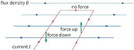
This is a useful idea, because it saves us thinking about the field due to the current. In Figure 24.18, we can see that there is only a force when the current cuts across the magnetic field lines.
This force is very important – it is the basis of electric motors. Worked example 1 shows why a currentcarrying coil placed in a magnetic field rotates.
WORKED EXAMPLE
1) An electric motor has a rectangular loop of wire with the dimensions shown in Figure 24.19. The loop is in a magnetic field of flux density $0.10 T$. The current in the loop is $2.0 A$. Calculate the torque (moment) that acts on the loop in the position shown.
Figure 24.19: A simple electric motor – a current-carrying loop in a magnetic field.
Step 1: The quantities we know are:
$B = 0.10 T$, $I = 2.0 A$ and $L = 0.05 m$ Step 2: Now we can calculate the force on one side of the loop using the equation
$F = BIL$:
$\begin{array}{l}
F = 0.10 \times 2.0 \times 0.05\\
= 0.10N
\end{array}$ Step 3: The two forces on opposite sides of the loop are equal and anti-parallel. In other words, they form a couple. From Chapter 4, you should recall that the torque (moment) of a couple is equal to the magnitude of one of the forces times the perpendicular distance between them. The two forces are separated by $0.08 m$, so:
$\begin{array}{l}
torque = force \times seperation\\
= 0.01 \times 0.08\\
= 8.0 \times {10^{ - 4}}N\,m
\end{array}$
Questions
10) A wire of length $50 cm$ carrying a current of $2.4 A$ lies at right angles to a magnetic field of flux density $5.0 mT$. Calculate the force on the wire.
11) The coil of an electric motor is made up of 200 turns of wire carrying a current of $1.0 A$. The coil is square, with sides of length $20 cm$, and it is placed in a magnetic field of flux density $0.05 T$.
a: Determine the maximum force exerted on the side of the coil.
b: In what position must the coil be for this force to have its greatest turning effect?
c: List four ways in which the motor could be made more ‘powerful’ – that is, have greater torque.
At an angle other than ${90^ \circ }$
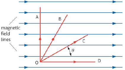
Now we must consider the situation where the current-carrying conductor cuts across a magnetic field at an angle other than a right angle. In Figure 24.20, the force gets weaker as the conductor is moved round from OA to OB, to OC and finally to OD. In the position OD, there is no force on the conductor. To calculate the force, we need to find the component of the magnetic flux density B at right angles to the current. This component is $B\sin \theta $, where $\theta $ is the angle between the magnetic field and the current or the conductor. Substituting this into the equation $F = BIL$ gives:
$F = (B\,IL\sin \theta )\,IL$
KEY EQUATION
$F = B\,IL\sin \theta \,$
Force on a current-carrying conductor.
or simply:
$F = B\,IL\sin \theta \,$
Now look at Worked example 2.
.Figure 24.20: The force on a current-carrying conductor depends on the angle it makes with the magnetic field lines
WORKED EXAMPLE
2) A conductor OC (see Figure 24.20) of length $0.20 m$ lies at an angle $\theta $ of ${25^ \circ }$ to a magnetic field of flux density $0.050 T$. Calculate the force on the conductor when it carries a current of $400 mA$. Step 1: Write down what you know, and what you want to know:
$\begin{array}{l}
B = 0.050\,T\\
L = 0.20\,m\\
I = 400\,mA\,( = 0.40\,A)\\
\theta = {25^ \circ }\\
F = ?
\end{array}$ Step 2: Write down the equation, substitute values and solve:
$\begin{array}{l}
F = BIL\,\sin \theta \\
= 0.050 \times 0.40 \times 0.20 \times \sin \,{25^ \circ }\\
\approx 1.7 \times {10^{ - 3}}\,N
\end{array}$ Step 3: Give the direction of the force. The force acts at ${90^ \circ }$ to the field and the current, i.e.
perpendicular to the page. The left-hand rule shows that it acts downwards into the plane of the paper.
Note that the component of B parallel to the current is $B\cos \theta $, but this does not contribute to the force; there is no force when the field and current are parallel. The force F is at right angles to both the current and the field.
Question
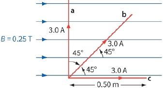
12) What force is exerted on each of the currents shown in Figure 24.21, and in what direction does each force act?
Figure 24.21: Three currents in a magnetic field. For Question 12